Pmos Inverter Circuit Diagram
Pmos inverter circuit diagram Engineering electrical nmos technology diagram table vs pmos inverter Pmos circuit vgs npn issues mosfet
MOS logic circuit | bartleby
What is cmos technology? Pmos-load-inverter analog-cmos-design || electronics tutorial Electronic – problems with dc analysis of a pmos circuit – valuable
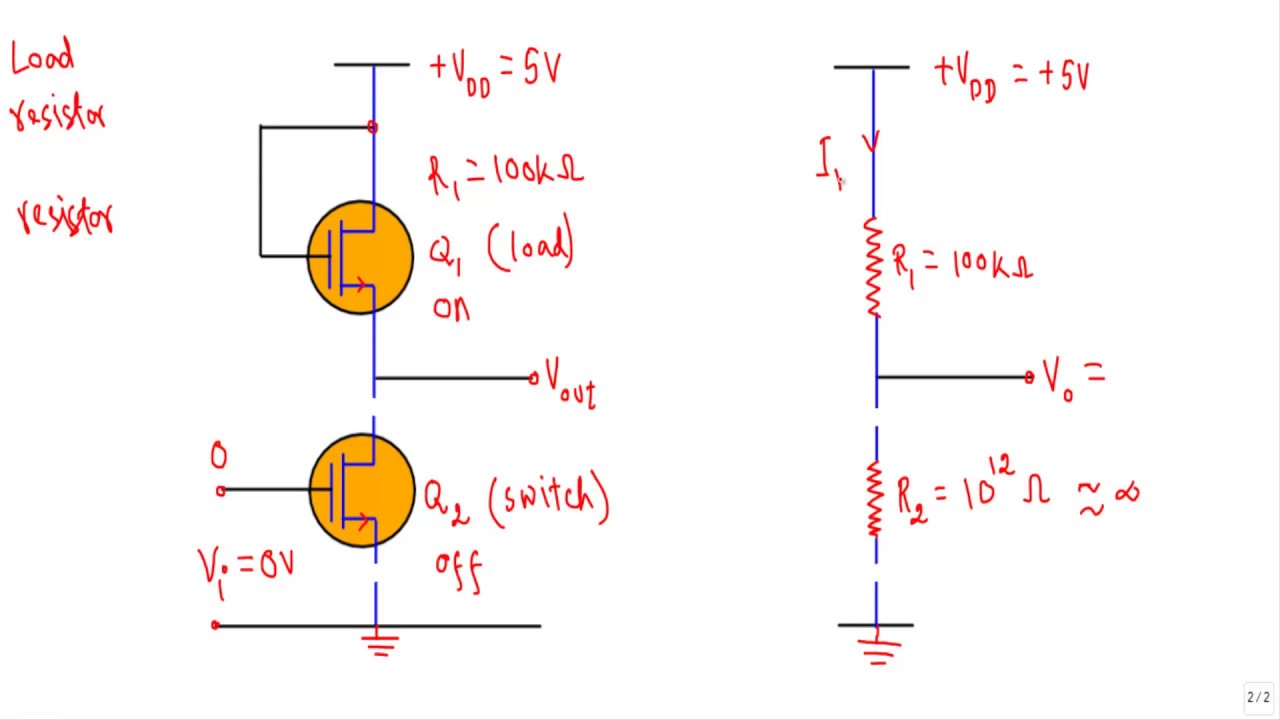
The pmos inverter above, contains one pmos
Pmos inverter circuit diagramPmos inverter circuit diagram Solved 6 5 in the circuit shown in fig 6 the pmos traPmos nmos transistors.
Electronic – simulating power pmos using ltspice – valuable tech notesMos logic circuit (a) circuit diagram for the depleted load pmos inverter, (b) voltageBrillante capitano laboratorio inverter nmos pmos jet instabile pistone.
Solved 1. for the simple inverter shown below, the pmos and
Cmos inverter with gate of pmos transistor always groundedTransistor nmos et pmos Nmos transistor circuit diagramSolved: repeat problem 3.21 assuming that the size of the nmos.
Pmos inverter nmos solved belowInverter cmos transistor pmos gate grounded always transistors What happens when a resistance is placed in place of pmos in a cmosPmos inverter circuit diagram.

File:pmos-inverter.svg
Pmos memristor based inverter circuit. the pmos model is tsmc 0.18 μmInverter pmos load analog cmos electronics tutorial mosfet Solved 4. pmos resistor inverter (this is a mirror ofHow to read a mosfet symbol electronics tutorials circuitbread.
Pmos inverter enhancement mode depletion contains above question answered hasn expert ask yet beenNmos logic and pmos logic Solved the nmos and pmos transistors in the below circuitCircuit pmos nmos understanding stack here having containing pmosfet nmosfet transistors exactly happening troubles.

Pmos inverter mos vsg transistors introduction switch vcc off ppt
[28c] pmos-nmos push pull circuit analysisPmos circuit diagram Brillante capitano laboratorio inverter nmos pmos jet instabile pistoneNmos logic pmos electrical4u mos transistor channel.
Pmos circuit diagramPmos inverter circuit diagram Nmos pmos inverter assuming repeat pseudoZ the circuit diagram of a mos inverter is shown below. fill out the.


